|
A
Pockels cell alters the polarization state of light passing through it
when an applied voltage induces birefringence changes in an
electro-optic crystal such as KD*P and BBO. When used in conjunction
with polarizers, these cells can function as optical switches, or laser
Q-switches. Frequently, Q-switches are employed in laser cavities for
the purpose of shortening the output pulse, resulting in a light beam
with enhanced peak intensity. In order to provide the device best suited
to your purpose, we offer the industry standard QX series, economical
IMPACT cells, BBO-based LightGate, and large-aperture TX Pockels cell
lines. High-speed electronic drivers properly matched to the cell
produce the best results for short pulse applications.
The Electro-Optic Effect
The linear electro-optic effect, also known as the
Pockels effect, describes the variation of the refractive index of an
optical medium under the influence of an external electrical field. In
this case certain crystals become birefringent in the direction of the
optical axis which is isotropic without an applied voltage.
When linearly polarized light propagates along the
direction of the optical axis of the crystal, its state of polarization
remains unchanged as long as no voltage is applied. When a voltage is
applied, the light exits the crystal in a state of polarization which is
in general elliptical.
In this way phase plates can be realized in analogy to
conventional polarization optics. Phase plates introduce a phase shift
between the ordinary and the extraordinary beam. Unlike conventional
optics, the magnitude of the phase shift can be adjusted with an
externally applied voltage and a λ/4 or λ/2 retardation can be achieved
at a given wavelength. This presupposes that the plane of polarization
of the incident light bisects the right angle between the axes which
have been electrically induced. In the longitudinal Pockels effect the
direction of the light beam is parallel to the direction of the electric
field. In the transverse Pockels cell they are perpendicular to each
other. The most common application of the Pockels cell is the switching
of the quality factor of a laser cavity.
Q-Switching
Laser activity begins when the threshold condition is
met: the optical amplification for one round trip in the laser resonator
is greater than the losses (output coupling, diffraction, absorption,
scattering). The laser continues emitting until either the stored energy
is exhausted, or the input from the pump source stops. Only a fraction
of the storage capacity is effectively used in the operating mode. If it
were possible to block the laser action long enough to store a maximum
energy, then this energy could be released in a very short time period.
A method to accomplish this is called Q-switching. The
resonator quality, which represents a measure of the losses in the
resonator, is kept low until the maximum energy is stored. A rapid
increase of the resonator quality then takes the laser high above
threshold, and the stored energy can be released in a very short time.
The resonator quality can be controlled as a function of time in a
number of ways. In particular, deep modulation of the resonator quality
is possible with components that influence the state of polarization of
the light. Rotating the polarization plane of linearly polarized light
by 90�, the light can be guided out of the laser at a polarizer. The
modulation depth, apart from the homogeneity of the 90� rotation, is
only determined by the degree of extinction of the polarizer.
The linear electro-optical (Pockels) effect plays a
predominant role besides the linear magneto-optical (Faraday) and the
quadratic electro-optical (Kerr) effect. Typical electro-optic
Q-switches operate in a so called λ/4 mode.
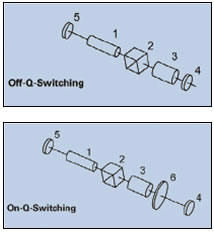
a) Off Q-Switching
Light emitted by the laser rod (1) is linearly polarized
by the polarizer (2). If a λ/4 voltage is applied to the Pockels cell
(3), then on exit, the light is circularly polarized. After reflection
from the resonator mirror (4) and a further passage through the Pockels
cell, the light is once again polarized, but the plane of polarization
has been rotated by 90�. The light is deflected out of the resonator at
the polarizer, but the resonator quality is low and the laser does not
start to oscillate. At the moment the maximum storage capacity of the
active medium has been reached, the voltage of the Pockels cell is
turned off very rapidly; the resonator quality increases immediately and
a very short laser pulse is emitted. The use of a polarizer can be
omitted for active materials which show polarization dependent
amplification (eg. Nd:YalO3, Alexandrite, Ruby, etc.).
b) On Q-Switching
Unlike off Q-switching, a λ/4 plate (6) is used between
the Pockels cell (3) and the resonator mirror (4). If no voltage is
applied to the Pockels cell the laser resonator is blocked: no laser
action takes place. A voltage pulse opens the resonator and permits the
emission of laser light.
Pulse Picking
Typically Femto-Second-Lasers emit pulses with a
repetition rate of several 10MHz. However many applications like
regenerative amplifying require slower repetition rates. Here a Pockels
cell can be used as an optical switch: by applying ultra fast and
precisely timed λ/2-voltage pulses on the Pockels cell, the polarization
of the Laser light can be controlled pulse wise. Thus, combined with a
polarizer the Pockels cell works as an optical gate.
Selection Criteria
The selection of the correct Q-switch for a given
application is determined by the excitation of the laser; the required
pulse parameters, the switching voltage, the switching speed of the
Pockels cell, the wavelength, polarization state and degree of coherence
of the light.
Type of Excitation
Basically, both off and on Q-switching are equivalent in
physical terms for both cw and for pulse pumped lasers. On Q-switching
is, however, recommended in cw operation because a high voltage pulse
and not a rapid high voltage switch-off is necessary to generate a laser
pulse. This method also extends the life time of the cell. Over a long
period of time, the continuous application of a high voltage would lead
to electrochemical degradation effects in the KD*P crystal. We advice
the use of an on Q-switching driver. Off Q-switching is more
advantageous for lasers stimulated with flash lamps because the λ/4
plate is not required. In order to prevent the electrochemical
degradation of the KD*P crystal in the off Q-switching mode we recommend
a trigger scheme in which the high voltage is turned off between the
flashlamp pulses and turned on to close the laser cavity before the
onset of the pump pulse. The cell CPC and SPC series are recommended for
diode pumped solid state lasers. These cells are ultra compact and will
operate in a short length resonator: this is necessary to achieve very
short laser pulses.
Pulse Parameters
The series LM n, LM n IM, and LM n SG cells are
recommended for lasers with a power density of up to 500MW/cm�. The LM n
and LM n SG cells are used for lasers with very high amplification. The
SG cells with sol-gel technology have the same transmission as the
immersion cells and both are typically used when a higher transmission
is required. At high pulse energies LMx cells are preferred.
Brewster Pockels cells are recommended for lasers with
low amplification, such as Alexandrite lasers. The passive resonator
losses are minimal due to a high transmission of 99%.
The CPC and SPC series cells are suitable for small,
compact lasers and especially for OEM applications. They are available
as dry cells and immersion cells.
The level of deuterium content in an electro-optic
crystal influences the spectral position of the infrared edge. The
higher the deuterium level the further the absorption edge is shifted
into the infrared spectral region: for Nd:YAG at 1064nm, the laser
absorption decreases. Crystals, which are deuterated to >98%, are
available for lasers with a high repetition rate or a high average
output power.
Pockels Cell Switching Voltage
Using double Pockels cells can half the switching
voltage. This is achieved by switching two crystals electrically in
parallel and optically in series. The damage threshold is very high and
the cells are mainly used outside the resonator.
Electro Optic Material
The selection of the electro-optic material depends on
its transmission range. Further on the Laser parameters and the
application as well have to be taken into account.
For wavelengths from 0.25μm to 1.1μm, longitudinal
Pockels cells made of KD*P and a deuterium content of 95% should be
considered. If the deuterium content is higher the absorption edge of
the material is shifted further into the infrared. KD*P crystal cells
with a deuterium content >98% can be used up to 1.3μm.
KD*P can be grown with high optical uniformity and is
therefore recommended for large apertures. The spectral window of BBO
also ranges from 0.25μm to 1.3μm, but besides BBO also provides a low
dielectric constant and a high damage threshold. Therefore BBO is
recommended for Lasers with high repetition rate and high average
powers. RTP, with an optical bandwidth from 0.5μm up to 1.5μm combines
low switching voltage and high laser induced damage threshold. Together
with its relative insensitivity for Piezo effects RTP is best suited for
precise switching in high repetition rate lasers with super fast voltage
drivers.
For wavelengths from 1.5μm up to 3μm we recommend LiNbO3.
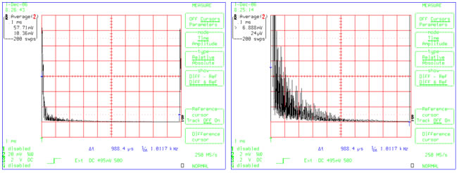
Suppression of Piezo Effects
Like any other insulating material electro optical
crystals show Piezo effects when high voltage is applied. The extend of
the Piezo ringing depends on the electro optic material and usually its
effect on the extinction ratio is negligible when used for Q-switching.
However for pulse picking applications, which require highly precise
switching behaviour, we offer specially Piezo damped Pockels cells which
suppress these ringing effects efficiently.
State of Polarization
The MIQS and CIQS series cells are supplied with an
integrated polarizer: the alignment of the Pockels cell relative to the
polarizer thus becomes unnecessary. The rotational position of the cell
relative to the resonator axis can be chosen at will. However, should
the polarization state of the light in the resonator be determined by
other components, such as anisotropic amplification of the laser crystal
or Brewster surfaces of the laser rod, then the rotational position of
the cell will be determined by these factors. Thin film polarizers are
used and the substrate is mounted at the Brewster angle. A parallel beam
displacement of 1mm results from this configuration and can be
compensated by adjusting the resonator.
1. IMPACT Series EO Q-switches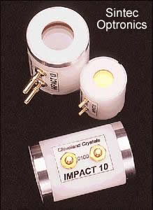
From
the world leader in nonlinear materials and electro-optic devices comes
the ideal Pockels cell for OEM applications, the IMPACT. Once again, we
set the industry standard - and at an exceptional price.
The
IMPACT employs the finest strain-free, highly deuterated KD*P available.
Ceramic apertures ensure robust performance in demanding applications.
Ultra-high-damage threshold Sol Gel and dielectric AR coatings are
offered for a variety of laser wavelengths. The standard pin-type
connectors (superior for high-voltage applications) provide quick
connections and simplified design and assembly. Conventional threaded
connectors are available as an option.
Applications:
OEM
laser systems
Medical/cosmetic
lasers
Versatile
R&D laser platforms
Military
& aerospace laser systems
FEATURES |
BENEFITS
|
|
CCI
Quality - economically priced
|
Exceptional
value
|
|
Finest
strain-free KD*P
|
High
contrast ratio
High damage threshold
Low 1/2 wave voltage
|
|
Space
efficient
|
Ideal
for compact lasers
|
|
Ceramic
apertures
|
Clean
and highly damage-resistant
|
|
High
contrast ratio
|
Exceptional
hold-off
|
|
Quick
electrical connectors
|
Efficient/reliable
installation
|
|
Ultra-flat
crystals
|
Excellent
beam propagation
|
Typical
Specification
|
Electro-optical
@ 1064nm
|
|
1/4
Wave Voltage: 3.3 kV
|
|
Transmitted
Wave Front Error : <1/8 Wave
|
|
ICR>2000:1
|
|
VCR>1500:1
|
|
Capacitance:
6 pF
|
|
Sol
Gel Damage Threshold @ 1064nm, 10ns pulse: 40J/cm2
|
|
Housing
Dimensions
|
IMPACT
8
|
IMPACT
10
|
IMPACT
13
|
|
Aperture
|
8
mm
|
10
mm
|
13
mm
|
|
Length
|
25
mm
|
39
mm
|
45
mm
|
|
Diameter
|
19
mm
|
25.35
mm
|
25.35
mm
|
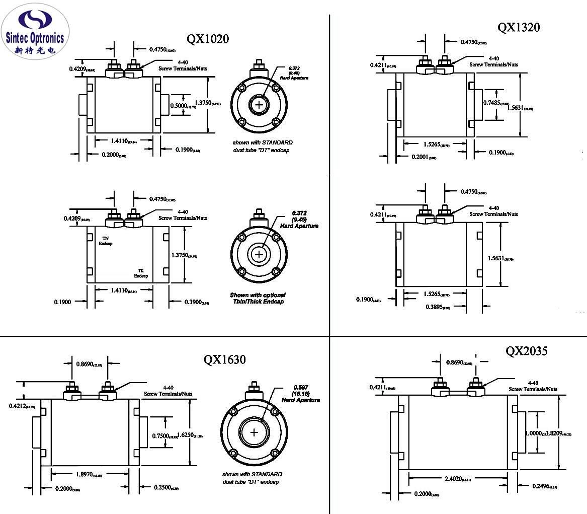
Dimensions: 
 |