|
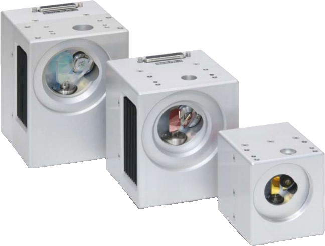
A whole laser marking
head (or called laser scanner) consists of two scan mirrors, two
galvanometers (or called galvo-scanner motor) & drive cards, a XY
mount, a scanning lens (f-theta lens), an interface card (or called
D/A card), a set of marking software and a DC power supply. Two
types of scanning optics for CO2 and Nd:YAG lasers are available.
Basics of 2-axis laser scanners
A laser beam is reflected from two scan mirrors in
turn, and directed through a focusing lens. The mirrors are capable
of high speed deflection about a rotation axis, being driven by a
galvo-scanner motor. In most cases the maximum deflection angle of
the mirror is �12.5� (often �10� is a safer limit) either side of
the non-deflected incidence angle of 45�.
Note
that, for best performance, the lens will appear to be �the wrong
way round� when compared with a standard meniscus lens used in
conventional focusing of a laser beam.
Some of the design objectives in specification of
2-axis laser scanners are:
-
Achievement of desired scanned field size
-
Maximization of scan speeds
-
Minimizing focused spot sizes
-
Lowest cost solutions
Some of the limitations to be considered are:
-
Quality factor Q (Q = M2)
of the laser beam
-
Scan angle limitations
-
Loss of power due to beam-clipping
-
Physical aperture of the scanner head
Field of scan
The laser beam will be scanned over an angle q, equal
to twice the mirror deflection angle. So, the typical scanned field
might be q=�20� in both X and Y directions. (q=�25� would be the
usual maximum scanned field). The field size is then approximately
2Ftanq in both X and Y.
The approximation arises because:
1) it is usually desirable to have a deliberate
distortion characteristic in the scanner lens design so that the
field position is proportional to q, not tanq.
2) scanning in two axes produces a geometrical
distortion which is unrelated to the lens properties.
Focused spot size
The lower limit on spot size �d� (1/e2
intensity diameter) for a laser beam of diameter �D� (1/e2)
is:
d = 13.5QF/D mm
Example: A TEM00 beam (Q=1) of 13.5mm (1/e2)
diameter, focused by a perfect lens of 100mm focal length, will form
a focused spot of 100mm diameter. (Taking a more realistic value of
Q=1.5, the spot size would be 150mm).
Beam clipping and optical aberrations can lead to
focused spot sizes which are larger than the minimum diffraction
limited value found from the equation above.
Large field sizes demand the use of lenses of long
focal length. In turn, this leads to increased focused spot size
unless the beam diameter, mirror sizes, and lens diameter are all
increased.
Spot sizes are given in the form of an average spot
size over the whole, maximum, field-of-scan. A second figure, the
standard deviation from average spot size, gives a measure of
variation of the spot size to be expected over the field.
Beam clipping
The physical aperture of a laser scanner is often
limited by a circular aperture of the scanner head, of diameter �A�
mm, say.
Beam clipping can occur at a circular aperture, even
for a well-centred beam, when the �tails� of the beam energy
distribution is blocked by the metalwork. The percentage power loss
at a circular aperture, for a TEM00 beam (Q=1) is shown
in the following table:
Table: Power Loss
|
A/D |
0.8 |
1 |
1.2 |
1.4 |
1.6 |
1.8 |
2 |
|
Loss % |
27.8 |
13.5 |
5.6 |
1.98 |
0.6 |
0.15 |
0.03 |
The table indicates that, where the physical aperture
of the scanner is limited to A mm diameter, the laser beam diameter
D (1/e2) must be selected by a compromise between reduced
spot size and power loss due to beam clipping. A value of D = A/1.4
would probably be acceptable for most laser scanner systems. Power
loss due to beam clipping increases for de-centred beams.
Mirror design
Mirror (1) (or called Scan Mirror X)
The width of mirror (1) is determined by the beam
diameter. It is easier to discuss this in terms of a �full beam
diameter� DF, where the definition of full diameter is,
to some extent, arbitrary.
For example, a system designer might define DF
as the measured diameter of a beam print in perspex [plexiglass].
Alternatively, DF may be the measured 99% power points,
or perhaps a value chosen in the range 1.4D to 1.6D.
The mirror width W1 is slightly larger than the
selected value of DF, sufficient to allow for minor
misalignment. The length of mirror (1) is determined by the maximum
angle of incidence imax on the mirror. Let a= (90�-imax).
Then the mirror length is L1, where L1 = W1/sina. The large shape
�chamfers� on scanner mirrors are determined by the separation, S1,
between mirrors (1) and (2); the scan angles, and the need that the
mirrors should not collide during scanning.
Mirror (2) (or called Scan Mirror Y)
The width of mirror (2), W2, should be identical to
the length of mirror (1). The length, L2, of mirror (2) is found
from projection of the beam onto the second mirror at a distance of
S1, and at maximum scan angle q. These mirrors are built and coated
specifically for use with CO2 or YAG lasers. They have a very
high laser damage threshold, measured at 1000W/mm of 1/e2
beam diameter (D).
F-theta characteristic
Lenses described as being �F-theta�, or �Fq�, type
are designed so as to produce an off-axis spot at a location
proportional to the scan angle. In turn, this may be directly
proportional to a voltage applied to the galvo scanner motor. (A
lens with zero distortion would form a spot at a field location of
Ftanq). No 2-axis galvo scanner can have a true F-theta
characteristic, due to distortion from use of two mirrors.
Single-element lenses are designed to be the best compromise between
smallest spot size and F-theta characteristic. Errors in F-theta
characteristic are usually 2% - 3% for these single element lenses.
Multi-element lenses allow design freedom enabling a closer approach
to F-theta performance. Fq errors <0.36% are typical for this range,
with only the 75mm FL type having a slightly greater value.
Lens design
All scanning lens designs are based on factors
described above. For typical small scanner systems, limited to
perhaps 10mm or 15mm full beam diameter, lenses of 48mm diameter
have been found to be suitable. For 15mm beams, this lens size is
only possible by minimizing the distances S1 and M2L. Each class of
lens is designed for use with a specific range of beam diameters,
and, more importantly, for a specific set
of values S1 and M2L.
In each case the lens is designed to provide the best
compromise performance for flat field, spot size and F-theta
characteristic for the specified beam diameter and mirror locations,
while avoiding beam-clipping at the lens mount.
For certain (longer focal length, single-element)
lenses it is possible to obtain an improvement in performance by
increasing the distance M2L. This necessitates the design/use of
lenses of larger diameter (to avoid beam clipping).
Options
Beam expander
Description of Part Number: LSxx-xxxx-yy-zzz-AAAA-BB
LSxx:
laser scanner. xx means the galvos such as ST, CT, SL or HL.
xxxx:
laser wavelength.
yy:
maximum input laser beam diameter.
zzz:
marking field, which depends on the used f-theta lens.
AAAA:
galvo model number
BB:
outlines and dimensions
CO2
laser marking heads at 10.6um
|
Part number |
Wave-
length
um |
Max input beam dia. mm |
Mark area
mm |
Focused beam dia.
um |
Model of galvo |
Outline |
Dimension
LxWxH,mm |
|
LSST-10.6-10-105-8161-2A |
10.6 |
10 |
105x105 |
171 |
OSST8161 |
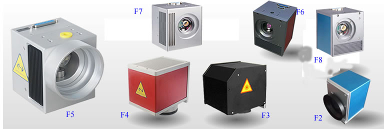
F2 |
128X98X92 |
|
LSST-10.6-12-105-8062-2B |
10.6 |
12 |
105x105 |
171 |
OSST8062 |
F2 |
155X118X128 |
|
LSST-10.6-12-105-8062-3A |
10.6 |
12 |
105x105 |
171 |
OSST8062 |
F3 |
155X118X128 |
|
LSST-10.6-15-105-8061-3B |
10.6 |
15 |
105x105 |
171 |
OSST8061 |
F3 |
180X145X148 |
|
LSST-10.6-20-105-8061-3B |
10.6 |
20 |
105x105 |
171 |
OSST8061 |
F3 |
180X145X148 |
|
LSST-10.6-25-105-3808-2C |
10.6 |
25 |
105x105 |
171 |
OSST3808 |
F2 |
205X162X178 |
|
LSST-10.6-32-105-3808-2C |
10.6 |
32 |
105x105 |
171 |
OSST3808 |
F2 |
205X162X178 |
|
LSCT-10.6-12-105-6230 |
10.6 |
12 |
105x105 |
171 |
6230 |
F4 |
165x124x136 |
|
LSCT-10.6-12-105-6231 |
10.6 |
12 |
105x105 |
171 |
6231 |
F4 |
165x124x136 |
|
LSSL-10.6-7-105-XS |
10.6 |
7 |
105x105 |
171 |
OSSL-XS |
F5 |
78x69x77 |
|
LSSL-10.6-10-105-S |
10.6 |
10 |
105x105 |
171 |
OSSL-S |
F5 |
115x96x94 |
|
LSSL-10.6-14-105-M |
10.6 |
14 |
105x105 |
171 |
OSSL-M |
F5 |
133x99x105 |
|
LSHL-10.6-10-105-S10A |
10.6 |
10 |
105x105 |
171 |
S10A |
F6 |
143x123x113 |
|
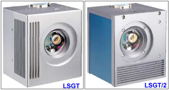
LSGT-10.6-10-105-S10B |
10.6 |
10 |
105x105 |
171 |
S10B |
F7 |
140x116x105 |
|
LSGT/2-10.6-10-105-S10B |
10.6 |
10 |
105x105 |
171 |
S10B |
F8 |
145x125x115 |
F-theta
lens
STSL-10.6-105-150 is used in above specifications.
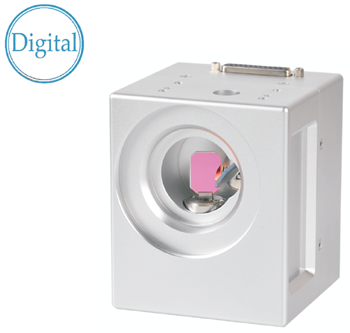
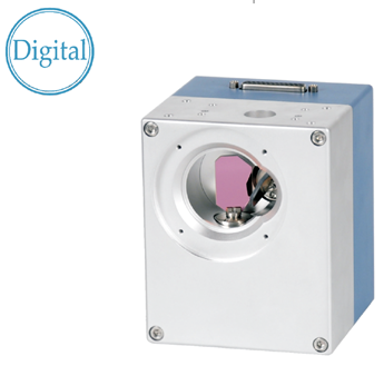
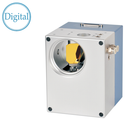
LSSL, LSHL & LSGT marking heads are digital heads and their port is
XY2-100.
Nd:YAG
laser and fiber laser marking heads at 1064nm
|
Part number |
Wave-
length
um |
Max input beam dia.
mm |
Mark area
mm |
Focused beam dia.
um |
Model of galvo |
Outline |
Dimension
(LxWxH,
mm) |
|
LSST-1064-12-110-8062-2B |
1064 |
12 |
110x110 |
18 |
OSST8062 |
F2 |
155X118X128 |
|
LSST-1064-12-110-8062-3A |
1064 |
12 |
110x110 |
18 |
OSST8062 |
F3 |
155X118X128 |
|
LSST-1064-15-110-8061-3B |
1064 |
15 |
110x110 |
18 |
OSST8061 |
F3 |
180X145X148 |
|
LSST-1064-20-110-8061-3B |
1064 |
20 |
110x110 |
18 |
OSST8061 |
F3 |
180X145X148 |
|
LSST-1064-25-110-3808-2C |
1064 |
25 |
110x110 |
18 |
OSST3808 |
F2 |
205X162X178 |
|
LSST-1064-32-110-3808-2C |
1064 |
32 |
110x110 |
18 |
OSST3808 |
F2 |
205X162X178 |
|
LSCT-1064-12-110-6230 |
1064 |
12 |
110x110 |
18 |
6230 |
F4 |
165x124x136 |
|
LSCT-1064-12-110-6231 |
1064 |
12 |
110x110 |
18 |
6231 |
F4 |
165x124x136 |
|
LSSL-1064-7-110-XS |
1064 |
7 |
110x110 |
18 |
OSSL-XS |
F5 |
78x69x77 |
|
LSSL-1064-10-110-S |
1064 |
10 |
110x110 |
18 |
OSSL-S |
F5 |
115x96x94 |
|
LSSL-1064-14-110-M |
1064 |
14 |
110x110 |
18 |
OSSL-M |
F5 |
133x99x105 |
|
LSHL-1064-10-110-S10A |
1064 |
10 |
110x110 |
18 |
S10A |
F6 |
143x123x113 |
|
LSGT-1064-10-110-S10B |
1064 |
10 |
110x110 |
18 |
S10B |
F7 |
140x116x105 |
|
LSGT/2-1064-10-110-S10B |
1064 |
10 |
110x110 |
18 |
S10B |
F8 |
145x125x115 |
Remark:
1) F-theta lens
STY-1064-110-160 is used in above specifications.
2) LSSL, LSHL & LSGT marking heads are digital heads
and their port is XY2-100.
Nd:YAG laser marking heads at 532nm
|
Part number |
Wave-
length
um |
Max input beam dia.
mm |
Mark area
mm |
Focused beam dia.
um |
Model of galvo |
Outline |
Dimension
(LxWxH,mm) |
|
LSST-532-10-110-8161-2A |
532 |
10 |
110x110 |
15 |
OSST8161 |
F2 |
128X98X92 |
|
LSST-532-12-110-8062-2B |
532 |
12 |
110x110 |
15 |
OSST8062 |
F2 |
155X118X128 |
|
LSST-532-12-110-8062-3A |
532 |
12 |
110x110 |
15 |
OSST8062 |
F3 |
155X118X128 |
|
LSST-532-15-110-8061-3B |
532 |
15 |
110x110 |
15 |
OSST8061 |
F3 |
180X145X148 |
|
LSST-532-20-110-8061-3B |
532 |
20 |
110x110 |
15 |
OSST8061 |
F3 |
180X145X148 |
|
LSST-532-25-110-3808-2C |
532 |
25 |
110x110 |
15 |
OSST3808 |
F2 |
205X162X178 |
|
LSST-532-32-110-3808-2C |
532 |
32 |
110x110 |
15 |
OSST3808 |
F2 |
205X162X178 |
|
LSCT-532-12-110-6230 |
532 |
12 |
110x110 |
18 |
6230 |
F4 |
165x124x136 |
|
LSCT-532-12-110-6231 |
532 |
12 |
110x110 |
18 |
6231 |
F4 |
165x124x136 |
|
LSSL-532-7-110-XS |
532 |
7 |
110x110 |
18 |
OSSL-XS |
F5 |
78x69x77 |
|
LSSL-532-10-110-S |
532 |
10 |
110x110 |
18 |
OSSL-S |
F5 |
115x96x94 |
|
LSSL-532-14-110-M |
532 |
14 |
110x110 |
18 |
OSSL-M |
F5 |
133x99x105 |
|
LSHL-532-10-110-S10A |
532 |
10 |
110x110 |
18 |
S10A |
F6 |
143x123x113 |
|
LSGT-532-10-110-S10B |
532 |
10 |
110x110 |
18 |
S10B |
F7 |
140x116x105 |
|
LSGT/2-532-10-110-S10B |
532 |
10 |
110x110 |
18 |
S10B |
F8 |
145x125x115 |
F-theta
lens
STY-532-110-160 is used in above specifications. LSSL,
LSHL & LSGT marking heads are digital heads and their port is
XY2-100.
Remark:
-
The marking
field of our standard marking
head
is 105x105mm (CO2 laser) or 110x110mm (Nd:YAG laser). Other mark
fields are available upon request. In fact,
the marking field depends on the f-theta lens. Thus you may
prepare a few f-theta lenses with different marking fields for
your various applications.
-
The focused beam
diameter is theoretical calculation for reference only and
actual focused beam diameter depends on beam expander, f-theta
lens and laser.
-
In LSCT series
marking heads, the galvos and drivers are made in the USA. In
LSSL series marking heads, the galvos, drivers and scan mirrors
are made in Germany.
-
All above
analogue marking heads can be converted into digital marking
heads via a D/A convertor as follows:
In order to meet the
experienced customers� requirement on cost, we also supply BASIC
laser marking head which just includes the basic parts such as
galvanometers and drivers, scan mirrors, DC power supply and all
mechanical parts. BASIC marking heads are integrated and aligned for
use. The model numbers will be LSCT-xxxx-yy-AAAA-BASIC or
LSST-xxxx-yy-AAAA-BASIC.
* Whole
marking head, including (1) integrated marking head (galvanometer &
its driver, scan mirror, f-theta lens and all mechanical parts.
Aligned for use. (2) marking card LMX-1 & marking software and (3) DC
power supply.
*
BASIC marking
head, including
integrated marking head (galvanometer
& its driver, scan mirror), DC power supply & all mechanical parts.
Aligned for use.
|


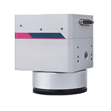 The
standard scan head for laser labeling
The
standard scan head for laser labeling